


Доступен к заказу
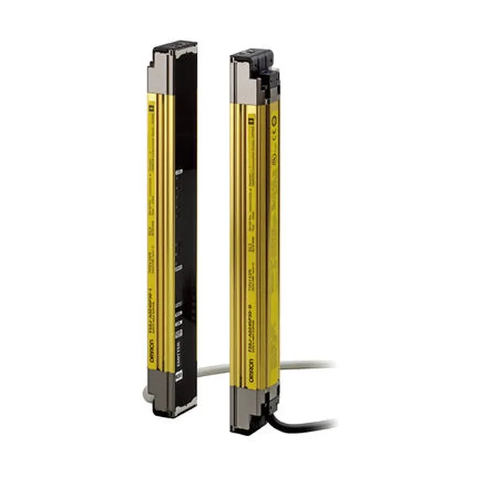
F3SJ-E0225P25
по запросу


Источник: proenergo.ru — © Промэнерго Автоматика · proenergo.ru

Семейство F3SJ-E — это световые барьеры безопасности типа 4 с разрешающей способностью 25 мм. Ширина барьера достигает 7 м, высота варьируется в пределах от 185 до 1105 мм, мертвая зона отсутствует.
| Application | Detection capability | Beam gap | Operating range | Protective height (mm) | Order code |
|---|---|---|---|---|---|
| Hand protection | Dia. 25 mm | 20 mm | 0.2 to 7 m | 185 to 1,105 | F3SJ-E____P25 |
| Number of beams | Protective height (mm) | Order code |
|---|---|---|
| 8 | 185 | F3SJ-E0185P25 |
| 10 | 225 | F3SJ-E0225P25 |
| 14 | 305 | F3SJ-E0305P25 |
| 18 | 385 | F3SJ-E0385P25 |
| 22 | 465 | F3SJ-E0465P25 |
| 26 | 545 | F3SJ-E0545P25 |
| 30 | 625 | F3SJ-E0625P25 |
| 34 | 705 | F3SJ-E0705P25 |
| 38 | 785 | F3SJ-E0785P25 |
| 42 | 865 | F3SJ-E0865P25 |
| 46 | 945 | F3SJ-E0945P25 |
| 50 | 1,025 | F3SJ-E1025P25 |
| 54 | 1,105 | F3SJ-E1105P25 |
Sensor mounting bracket
| Appearance | Specifications | Application | Remarks | Order code |
|---|---|---|---|---|
| Top/bottom bracket | Top/bottom bracket for F3SJ-E/B | 2 for an emitter, 2 for a receiver, total of 4 per set |
F39-LJB1 | |
| Intermediate bracket | In combination use with top/bottom bracket for F3SJ-E/B Can be used as free-location bracket. |
1 set with 2 pieces | F39-LJB2 | |
| Quick mount bracket | Quick mount bracket for F3SJ-E/B Supports M6 slide nut for aluminum frame. |
1 set with 2 pieces | F39-LJB3-M6 | |
| Quick mount bracket for F3SJ-E/B Supports M8 slide nut for aluminum frame. |
F39-LJB3-M8 | |||
| Quick mount M6 bracket Quick mount M8 bracket |
Bracket to mount an intermediate bracket to the aluminum frame with a single touch. |
Hexagon socket head cap screws (M6 × 10) are included. |
F39-LJB3-M6K | |
| Hexagon socket head cap screws (M8 × 14) are included. |
F39-LJB3-M8K | |||
| Compatible mounting bracket | Mounting bracket used when replacing existing area sensors (F3SJ-A or F3SN) with the F3SJ-E/B. |
2 for an emitter, 2 for a receiver, total of 4 per set |
F39-LJB4 | |
| Contact mount bracket | Bracket to closely contact the back side of the sensor. | 2 for an emitter, 2 for a receiver, total of 4 per set |
F39-LJB5 |
Laser pointer
| Appearance | Output | Order code |
|---|---|---|
| Laser pointer for F3SJ | F39-PTJ |
| Model | F3SJ-E____P25 | |
|---|---|---|
| Sensor type | Type 4 safety light curtain | |
| Setting tool connection | Parameter settings: Not available | |
| Safety category | Safety purpose of category 4, 3, 2, 1, or B | |
| Detection capability | Opaque objects 25 mm in diameter | |
| Beam gap (P) | 20 mm | |
| Number of beams (n) | 8 to 54 | |
| Protective height (PH) | 185 to 1,105 mm | |
| Lens diameter | Diameter 5 mm | |
| Operating range | 0.2 to 7 m | |
| Response time (under stable light incident condition) | ON to OFF | 15 ms max. |
| OFF to ON | 70 ms max. | |
| Startup waiting time | 2 s max. | |
| Power supply voltage (Vs) | SELV/PELV 24 VDC±20% (ripple p-p 10% max.) | |
| Consumption current (no load) | Emitter: Up to 22 beams: 41 mA max., 26 to 42 beams: 57 mA max., 46 to 54 beams: 63 mA max. Receiver: Up to 22 beams: 42 mA max., 26 to 42 beams: 47 mA max., 46 to 54 beams: 51 mA max. |
|
| Light source (emitted wavelength) | Infrared LED (870 nm) | |
| Effective aperture angle (EAA) | Based on IEC 61496-2. Within ±2.5° for both emitter and receiver when the detection distance is 3 m or over | |
| Safety outputs (OSSD) | Two PNP transistor outputs, load current 200 mA max., residual voltage 2 V max. (except for voltage drop due to cable extension), Leakage current 1 mA max., load inductance 2.2 H max., Maximum capacity load 1 μF | |
| Output operation mode | Safety output: On when receiving light | |
| Input voltage | ON voltage: Vs-3 V to Vs, OFF voltage: 0 V to 1/2 Vs or open | |
| Mutual interference prevention function | Mutual interference prevention algorithm prevents interference in up to 3 sets. | |
| Test function | Self test (at power-ON and at power distribution) External test (emission stop function by test input) |
|
| Protection circuit | Output short-circuit protection, and power supply reverse polarity protection | |
| Ambient temperature | Operating: -10 to 55°C (non-freezing), Storage: -25 to 70°C | |
| Ambient humidity | Operating: 35% to 85% (no condensation), Storage: 35% to 95% RH | |
| Operating ambient light intensity | Incandescent lamp: 3,000 lx max., Sunlight: 10,000 lx max. | |
| Insulation resistance | 20 MΩ min. (at 500 VDC) | |
| Dielectric strength | 1,000 VAC 50/60 Hz, 1 min | |
| Degree of protection | IP65 (IEC 60529) | |
| Vibration resistance | Malfunction: 10 to 55 Hz, Multiple amplitude of 0.7 mm, 20 sweeps in X, Y, and Z directions | |
| Shock resistance | Malfunction: 100 m/s2, 1,000 times each in X, Y, and Z directions | |
| Pollution degree | Pollution degree 3 (IEC 60664-1) | |
| Power cable | Connection method: Pull-out type, cable length 3 m Number of wires: Emitter: 5 wires, receiver: 6 wires Cable diameter: Dia. 6 mm Allowable bending radius: R5 mm |
|
| Extension cable | 30 m max. | |
| Material | Case: Aluminum Cap: ABS resin, PBT Optical cover: PMMA resin (acrylic) Cable: Oil resistant PVC |
|
| Weight (packed state) | Weight (g) = (protective height) × 2.6 + 800 | |
| Accessories | Test rod, Instruction Manual, User's Manual (CD-ROM) | |
| Applicable standards | IEC 61496-1, EN 61496-1 UL 61496-1, Type 4 ESPE (Electro-Sensitive Protective Equipment) IEC 61496-2, CLC/TS 61496-2, UL 61496-2, Type 4 AOPD (Active Opto-electronic Protective Devices) IEC 61508-1 to -3, EN 61508-1 to -3 SIL3 IEC 13849-1: 2006, EN ISO 13849-1: 2008 (PLe, Cat.4) UL 508, UL 1998, CAN/CSA C22.2 No.14, CAN/CSA C22.2 No.0.8 |
|